2016. február 29., hétfő

Temperature measurement and logging with an Arduino

Hungarian version.

I planned to measure the temperature changes of our electric water heater with an Arduino. Then I wanted to create a chart from the logged data. I planned this as I was curious how the temperature drops and raises as time passes.


Unfortunately because of the insulation there is no place to put the temperature sensor for measurement. This is the thermistor I get from a laptop battery. So this project has to be postponed.
Nevertheless the Arduino circuit is ready, I have the code as well, so I will share it with my readers. The code measures the temperature in the given time intervals, then it stores them in the internal memory. This EEPROM is limited however to 1024 Byte on my Arduino, so I can only save 1024 times, a number between 0-256. If I take a measurement in every 30 seconds, then it is enough to log the data for 8 hours. The data will not be lost if we turn of the Arduino.

An 10000 Ohm resistor and a thermisor is required. The picture shows how to connect the parts.

I have soldered a longer cable on the thermistor for easier handling:


Code for temperature measurement:

#include <EEPROM.h>

// we have to define which analog input we want to use
#define THERMISTORPIN A0
// we have to set the memory address to 0 as the first address
int addr = 0;

void setup(void) {
  Serial.begin(9600);
  pinMode(13, OUTPUT);
}
 
void loop(void) {
  
  float reading;
  //we take a measurement
  reading = analogRead(THERMISTORPIN);
  //here we divide it with 4 as we can only save a number between 0-256
  int val = analogRead(THERMISTORPIN) / 4;
  // we save the value
  EEPROM.write(addr, val);
  //we jump to the next address
  addr = addr + 1;
  if (addr == EEPROM.length()) {
    addr = 0;
  }  
  //we wait 30 seconds then we take an other example
  delay(30000);
}

Code to read out the memory contents:

/*
 * EEPROM Read
 *
 * Reads the value of each byte of the EEPROM and prints it
 * to the computer.
 * This example code is in the public domain.
 */

#include <EEPROM.h>
// the value of the 'other' resistor
// start reading from the first byte (address 0) of the EEPROM
int address = 0;
int value;
double Temp;
void setup() {
  // initialize serial and wait for port to open:
  Serial.begin(9600);
  while (!Serial) {
    ; // wait for serial port to connect. Needed for native USB port only
  }
}

void loop() {
  float reading;
  // read a byte from the current address of the EEPROM
  value = EEPROM.read(address);

  Serial.print(address);
  Serial.print("\t");
  Serial.print(value, DEC);
  Serial.print(" ");
  //we have to multiplicate it with 4 to get the initial measured value as we saved a value which were divided by 4
  value=value*4;
  Serial.print(value);
  //this is a formula to be used to convert the measured reading to celsius the calculation is from: https://en.wikipedia.org/wiki/Thermistor
  Temp = log(((10240000/value) - 10000));
  Temp = 1 / (0.001129148 + (0.000234125 * Temp) + (0.0000000876741 * Temp * Temp * Temp));
  Temp = Temp - 273.15;           // Convert Kelvin to Celcius  
   
  Serial.print(" Temperature "); 
  Serial.print(Temp);
  Serial.println(" *C");
  /***
    Advance to the next address, when at the end restart at the beginning.

    Larger AVR processors have larger EEPROM sizes, E.g:
    - Arduno Duemilanove: 512b EEPROM storage.
    - Arduino Uno:        1kb EEPROM storage.
    - Arduino Mega:       4kb EEPROM storage.

    Rather than hard-coding the length, you should use the pre-provided length function.
    This will make your code portable to all AVR processors.
  ***/
  address = address + 1;
  if (address == EEPROM.length()) {
    address = 0;
  }

  /***
    As the EEPROM sizes are powers of two, wrapping (preventing overflow) of an
    EEPROM address is also doable by a bitwise and of the length - 1.

    ++address &= EEPROM.length() - 1;
  ***/

  delay(50);
}

The first code has to be run first and we should wait for the data collection for the decided timeframe. Then the read out code can be run to get the results. As a test I have measured the radiator temperature changes for 6 hours. The outside temperature has dropped from 43 F to 37 F. The beginner temperature in the room was 73 F.


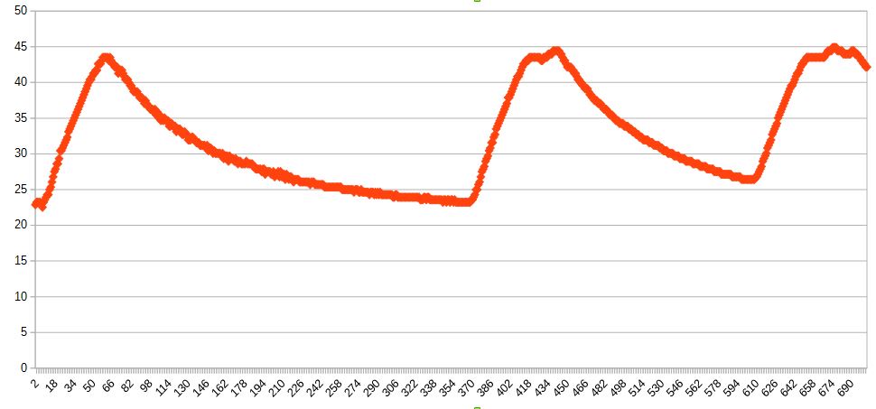
It is clearly visible that the radiator temperature rises very fast when the heating is on, then when it turns off, the temperature drops in an ever smaller scale until it reaches the room temperature. At the second and the third peak there is a slight temperature drop caused by the heating control. As the thermostat reaches the desired temperature it turns off the heating, but the water pump turns on again for a short period to take out the heat from the boiler.

2016. február 22., hétfő

Atomic clock on the nightstand

Hungarian version.

My friend gave me a non working digital clock so he said. It works from two AA 1,5V Alkaline battery. When I took it home, I tried to use it with one of the 18650 cells since I have some now and it worked! The curiosity of this clock is that it is radio controlled. This means that it is automatically synchronized by a time code transmitted by a radio transmitter connected to an atomic clock in Mainflingen, Germany. The code of this station is DCF77. This station is 500 miles away from my home and it sends the signal 24 hours a day. It sends the exact time and date as well. The photo of the station is a bit similar to the conspiracy theories American weather controller station. But I do not believe in such things. :) The transmitted signal is repeated in every minute and each second sends its own information bits. Hour, minute, day, month, year. They do not transmit the seconds, I guess the clock automatically adjusts the time to the beginning of a minute.

It is very interesting that they also send the signal of the summer time change and the so called leap second as well. A leap second is a one-second adjustment that is occasionally applied to Coordinated Universal Time (UTC) in order to keep its time of day close to the mean solar time, or UT1. Wiki link. This is something like the leap year. Last year there was a leap second added on 30th June at midnight, when the clocks showed 23:59:60 second instead of 00. But it is sometimes added on New Year’s Eve. The wiki page worth the reading, as this leap second have caused problems for some companies before. For example at the airplane control, as a plane can move 0,16 miles in one second.


Until now there was a 14 bits unused space, in Germany they are just trying to use it for emergency information broadcast. I think this is a good idea. I just need a receiver.

The reception area around Germany:


One can buy a receiver circuit for DCF77, but they are a bit expensive.

It is fascinating that today when there are clocks everywhere and in every device, no one cares about a clock which is as accurate as an atomic clock. How much they would have respected it in the beginning of the last century! It is a bit luxury to have this and it also feels a bit strange, that the clock on the nightstand is as accurate as an atomic clock. And it is for free as well.

What I also noticed that it not always able to synchronize itself with the transmitted signal. For instance my computer's electronic radiation prevents the synchronization. If I put the clock into the window it finds the signal very fast. There is a signal power meter on the LCD, it is very convenient.

Some words about this clock. It's brand is: home by somogyi . The company: Somogyi Elektronic Kft was established in 1991 in Hungary with headquarters in Győr. They practically buying parts and products from China and they put the somogyi brand on them.


Luckily it can handle 4V Li-ion voltage well.

Its power consumption facts:
basic power consumption: 0,01mA
when it is looking for the transmitted signal: 0,29mA
if the backlight shines: 50mA (unfortunately I have broken this when I opened it and I was not able to solder the panel back)

So it consumes very little power, which is consumed by the big display.


One can set two different alarm times on it. It looks like this when opened. It was manufactured at the end of 2007, so it is older than 8 years. The big coil is required to receive the transmitted signal. There is the quartz crystal in the middle, on the right there is the tweeter. There are three chips covered with resin or something as it is cheaper than to box them.

2016. február 21., vasárnap

Battery capacity measurement with an Arduino - In other words, let's discharge the batteries


Welcome everyone. Who has read my plan - that I will use the Keweisi capacity meter to measure my 18650 cell capacities - knows that I have chosen the Arduino solution, because it gives a more accurate reading. I have spent several days to find out what parts I need and what code do I have to run. I have analyzed several similar projects on the internet. I had to create a simple yet effective code. With my solution it is possible to measure the capacity of 1,2V Ni-MH, Ni-Cd and 3,7V Li-ion or polimer batteries. In fact you can measure the capacity of any battery with this design which has a voltage lower then 5V.

Ingredients:

-a microcontroller, in this case I used an Arduino Duemilanove. Of course it is not a genuine Italian one, it is an aftermarket model from China. I do not think this is still in production, the Uno model is the recent one, but not much has changed on it since. If someone has another type of microcontroller, my connection diagram will not help.

-a resistor. This should be rated at least 5W, so it will be able to bear the load. I have bought a 3,9 OHM and an 5,9 OHM ceramic resistor. The smaller OHM rating we use, the bigger the current will be to discharge the batteries. Why does it have to be 5W rated? It is because if for example the Voltage is 4V and I want to discharge with 1A current then the output is: 4V*1A=4W, this energy is turned into heat on the resistor. If we use OHM's law for calculation at 4V and with 3,9 OHM resistor, the Current will be 4V/3,9OHM=around 1A. Of course as the battery voltage decreases over time, the current will become smaller and smaller. If I use the 5,9 OHM resistor, then at 4V the current will be: 4V/5,9OHM=0,677A. I used the 4V example because a fully charged Li-ion cell gives around 4 volts. This was just an example. But if for instance I want to discharge an AAA 1,2V Ni-Mh battery, the numbers are the following, with a 3,9OHM resistor it will discharge it with 0,307A, which they can bear. I am not sure how much current they can give, but I think 0,3A is enough to prevent overheating. It seems they can bear 1A discharge current as well. You can now calculate the required resistor size if you know with how much current you want to discharge the battery.

-a MOSFET. I used one with three leads called: IRLU8256. This is required to open and close the discharge circuit controlled digitally with the Arduino. It is like a switch, but you can control it from the Arduino code. In case of a Li-ion battery you can turn the discharge off, to prevent over discharging.
Important characteristics: Vds=25V, so it can bear the voltage. Rds=around 5mOHM, here the smaller is better so it has a little resistance. Vgs should be little, so the Arduino 5V power is able to turn the FET on and off.

-a battery to be discharged. You can also buy battery holders, but used magnets to hold the wires on the battery. This is a cheaper solution.

That is all. I have read on the internet, that other designs also measure the voltage on the MOSFET and if there is any loss they use it as well for the current calculation. My MOSFET always gave 0V here, so I left it out.

The two other designs I used as inspiration: One, two.

Warning! The resistor heat up during discharge so it can burn your hand. Of course it will not burn, but it will be hot. Always use wires which can bear the load that you are using. It can happen that the MOSFET stays open and keeps discharging the batteries if we shut the Arduino off or if we stop the code run in the middle. Do not leave it unattended and make sure that it will not over discharge the batteries. I take no responsibilities for the damage this discharger may cause.

If there is no battery connected and the code runs, it will give false Voltage readings.

You can see on the pictures how to connect the wires. Although there are two batteries connected in series on the picture, this is only because there was no other picture in the program. I usually discharge one cell at a time.

Arduino code:

#define MIN_VOLTAGE      950   // mV, the voltage should not drop until this amount. At a Li-ionnál: 3000, with NI-MH:950

int FETPin = 13;      // select the digital output pin for the LED and the FET
int BatVoltage = 0;
int STOPI = 0;
float loadCurrent, TotalCurrent, TotalCurrent2, onescurrent;
int sec = 1;

void setup() {
  unsigned long PrevTime;
  Serial.begin(9600);// start serial port to send data during run to the PC
  pinMode(FETPin, OUTPUT);
  digitalWrite(FETPin, LOW); 
  Serial.println("6");	//countdown until the discharge process, I use this time to connect the battery
  delay(1000); 
  Serial.println("5");
  delay(1000); 
  Serial.println("4");
  delay(1000); 
  Serial.println("3");
  delay(1000); 
  Serial.println("2");
  delay(1000); 
  Serial.println("1");
  delay(1000); 
  
  Serial.println("START!");
  int val1 = analogRead(0); // we take an initial test to measure the initial voltage
  BatVoltage = map(val1, 0,1023,0,5000);;
  Serial.print("Starting voltage in mV=");
  Serial.println(BatVoltage + 40); // here I added 40 to the the measured voltage as the Arduino measuread an incorrect Voltage
}

void loop() {
  
  
  if(STOPI != 1){
    
    digitalWrite(FETPin, HIGH);  //here we active the the discharge circuit
    int val1 = analogRead(0); 
    BatVoltage = map(val1, 0,1023,0,5000);;
    
    loadCurrent = (BatVoltage + 40) / 3.9;              //at the end of the equation the exact resistor rating in OHM should be changed

    onescurrent =  loadCurrent / 3.6;		//here we calculate the Current amount load in a second
    TotalCurrent = onescurrent + TotalCurrent;
        
    Serial.print(BatVoltage + 40);   
    Serial.print(" mV   I=");
    Serial.print(loadCurrent);		//Current load amount per second
    Serial.print(" mA   Time=");
    Serial.print(sec);
    Serial.print(" s   Totalcurrent=");
    Serial.print(TotalCurrent / 1000);   // total mAh burnt
    Serial.println(" mAh");
    sec = sec + 1;
    if(BatVoltage + 40 <= MIN_VOLTAGE){
      STOPI = 1;
      Serial.println("Voltage is lower then the set min Voltage STOP!");
    }
  }
  else{
    digitalWrite(FETPin, LOW);  
  }
  delay(1000);  // wait one second, then get next set of samples  
}

The measured capacity is just an estimate, as the higher the discharge Current, the lower the measured capacity will be.

2016. február 18., csütörtök

2.part- 7800mAh genuine IBM Laptop battery teardown - Lenovo T60

Hungarian version.

Welcome everyone. This battery was made at the time when IBM has already sold its laptop business to Lenovo, but the IBM brand was still printed on these products. It is from August, 2006, so it is almost 10 years old. I red this from the battery markings. The battery was used in a T60 laptop. Its teardown was a bit harder than the noname battery I have already written about, because the case is stuck together better.

So the brand is IBM, it is 10,8V and has a capacity of 7,8Ah. As it has 9 cells, it can be calculated that each cell has 2600mAh capacity in it. The cells are Panasonic made and their specification says they have 2550mAh capacity each. If we take it nine times, we get only 7,65Ah capacity, which is slightly smaller than the indicated number on the case.

It looks like this when I have ripped it open. It is interesting how the third row is split a bit. I think this is only a design solution, it has no real purpose. 3 cells in series and 3 in parallel. There is the controlling circuit on the top and there is the heat sensor duck taped to one of the cells. That's all. Well, I have not expected anything else. 6 of the cells had 3,65V voltage, 3 of them had only 2,65V. The guy, from whom I get the cells, told me, that after a charging the battery would not work anymore. We will see if the cells are still in working condition or not.


In the noname battery I previously opened had a nicer controlling circuit. That had a red circuit board and was not covered with such rubber material.


The microcontroller chip is an M37512 together with a 61048FP. If you are interested their specifications you can search on Google. The heat fuse can also be found on the board, it looks slightly different like on the noname circuit.


The temperature sensor can measure only the top right cell's temperature. Maybe it is put there on purpose? Maybe that cell is the mostly used.


This is what is left from the battery, I will use the temperature sensor for other projects.


Here is the capacity list of the cells:

1370
1317
1192
1362
1264
1062
1001
1187
1031
mAh.

How to find out if the cells are in a good shape. For each cell:

1. Measure voltage, if it's less than 2.5v, do not use it.
2. If it gets hot during charging, do not use it.
3. After charging the voltage should be between 4.1v and 4.2v.
4. After 30 munutes if it's fallen less than 4v, do not use it. Note the measured voltage.
5. After 3 days, measure the voltage again, if voltage has fallen more than 0.1v from the recorded voltage, do not use it.

2016. február 17., szerda

1.part- Found aftermarket 4400mAh Laptop battery teardown - Lenovo G450

Hungarian version.

I am planning to build an electric bicycle Li-ion Battery pack. More people on the internet are using 18650 Li-ion battery cells found in Laptop batteries for this purpose. 18650 is a size standard, these are 3,7V cells with significant capacity. I have recently found a laptop battery in a dustbin and I though from the size of the battery that it contains 18650 cells. I have taken it home. It happens regularly that only 1 or 2 cells are faulty in the pack, but the others are still functional. Or just the control circuit shuts it down for some reason. In these cases the battery will not let to charge itself. This is the time when they get in the dustbin. But there are still some usable cells inside which can be used. Of course their capacity does not reach the manufacture capacity, but for hobby and project purposes they are still ideal. They can be also used in a flashlight, storing energy to recharge USB devices and so on. So let’s see.

As it does not have any brand it is a noname aftermarket piece. It is written on the outer shell that it contains Li-Ion cells and it has a capacity of 4400mAh and it gives 11,1V. The sticker on the side tells that it was manufactured in the middle of 2013. It has not been used for too long. Maybe it is because the cells are bad quality or the full battery capacity has decreased to a level that it was unable to give enough power to a laptop, or it would have run only for some minutes.


The case was easy to open at the joints. This process requires attention, not to damage the cells or to cause short circuit, as the cells may get overheated or set on fire. There are six cells in this battery.
They seems to be robust compared to an AAA or AA battery, they are bigger and heavier. Three are connected in series and three are connected with them in parallel. 3,7V*3=11,1V as it can be seen on the sticker. From the 4400mAh capacity indicated it is obvious that each cell is rated 2200mAh. The controlling circuit is located on the top right side. There is a temperature sensor duck taped to one of the cells.


It is simple plastic case. What is surprising is that if we take a closer look at this inner side, the initial numbers and markings can be seen from the mould which they used in the factory to manufacture this shape of plastic.


I have cut the cables connected to the controller circuit, then the strip which connected the cells together. We have to take care again, not to cause a short circuit. With the help of long nose pliers the metal strip can be torn off the cells. I used a circular motion to wind it down as I would open a tin can.


The other side of the case. The cells were glued in with hot glue.


The cells seem to be noname, nothing can be found out from their printings. I have searched with Google to SZN cells, a 2200mAh piece cost 3,6 USD in Hungary. The better quality branded ones costs around 5,3 USD each. I was wondering here about the laptop battery prices. A noname similar laptop battery costs in Hungary around 36 USD. A branded one costs around 72-108 USD. But what costs this much on the batteries? One cell costs 3,6USD. 6*3,6=21,6 USD. Plus the package and the controlling circuit. These cannot cost around 14,3USD, because in China they manufacture in huge quantities and in bulk it is way cheaper. So on each of the noname batteries, there is a profit around 10,8-14,4 USD. But I think it is much more. Now let's see the branded ones. Those cost 2-3 times the noname's price. But the branded cells are not cost this much more. Not even the controlling circuit. If we count 6USD*6=36USD if we count the best quality cell. Plus the controller. On the branded batteries there has to be more than 70USD profit on each. This is amazing.

Let's see if the cells are still in working condition or not. They say if a Li-ion cell's voltage drops below 2.5V then it is damaged unrecoverable. I have measured the voltage of these cells and all was on 4,1V! This is normal since while charging they are charged until 4,2V when they are full. So it is possible that all the cells are still functional.


The controlling circuit was made with modularity in mind. It can be seen on the left that this connector part can be changed depending on what type of laptop will it serve. So the other part of the circuit can be always the same. Of course the programming details are changing like how many cells are there, the capacity, the charging current and so on. The temperature sensor is checking if there is an overheating happening. But I think the temperature should be checked on all cells, because what if the one on the left gets too hot, until the sensor on the right senses it, it may be too late. Maybe the branded batteries have different design. The controlling chip is an Atmel MEGA406. You can find its specifications on the internet. There is one more interesting thing on the circuit. The small white cigarette shape with the white putty, it is a thermal fuse. If they reach the melting temperature they cut the circuit. Because it is intact this was not the cause of the dumping.

I have found something interesting on the internet. There is a chance to "reset" the controlling chip, so it will delete the stored information about the charging cycles and errors. It is possible that after resetting the battery would still work for some time. There is a manual about this here. In short it describes that if we search on the internet for the specifications of the controller chip, there is usually a reset leg on it, which in the mentioned case has to be connected with the battery ground wire. This would reset the chip. Please experiment on your own responsibility! Unfortunately I cannot try this on my battery, as I do not have a laptop to test it with.

To be frank I thought the batteries are more complicated inside, but they are not. They are also very expensive compared to what is inside them. I will keep the temperature sensor for future Arduino projects.


I have measured the cells capacity:

1- 659mAh
2- 51mAh
3- 1238mAh
4- 1303mAh
5- 780mAh
6- 875mAh

When they were new theoretically they had 2200mAh capacity. It is interesting that it has decreased in this magnitude in 2,5 years. We do not know it is because the battery was used too much, or the cells are bad quality cells. But the 51mAh cell proves that it had to perform very badly. I do not think it was capable to run a laptop in this state.

How to find out if the cells are in a good shape. For each cell:

1. Measure voltage, if it's less than 2.5v, do not use it.
2. If it gets hot during charging, do not use it.
3. After charging the voltage should be between 4.1v and 4.2v.
4. After 30 munutes if it's fallen less than 4v, do not use it. Note the measured voltage.
5. After 3 days, measure the voltage again, if voltage has fallen more than 0.1v from the recorded voltage, do not use it.

2016. február 14., vasárnap

DIY USB solar charger

Hungarian version.

I would like to show you my solar USB charger what I built in 2009. I have ordered from Ebay from China 6 solar panels for 64 USD. It would cost 72 USD today if we calculate inflation. I have put the panels into a DVD case, which is getting a bit worn in the past 7 years. I want to build a new case for them. By the way, who watches DVDs these days?


The Diode is hidden behind the duct tape.


These are 6V 133mA panels, so 0,8W per panel. So the six pieces I bought together is 4,8W for 72 USD. Today I could buy more than 35W power rated panels for the same price. In 7 years their price dropped to seventh of the original price!

I was thinking that 6V would be good to charge USB devices, because the USB specification suggests 5V. As it can be seen on the picture I used three panels and I connected the in parallel, so theoretically they will give out 400mA current. I have also put a diode in front of the USB connector to prevent the current flow to the panel direction.

The solar panels supply the specification ratings at ideal conditions and without any load on them. I was curious how much power they give under load. I have used my magic KEWEISI usb capacity meter to measure the voltage and current. It seems the three solar panel supply around 4.6V with 0,2A current. It is interesting that they supply around 10% less power if I used them in a horizontal position, not in an ideal angle. In horizontal angle they supply 4.5V with 0,15-0,17A.

As it charges very slowly, I barely used this charger. I usually use it if I go to a bicycle excursion and I am charging my PDA.


The funny thing is that, I have sold the three leftover solar panels on an auction site for double the price than I have paid for them, so the three I am using were for free. :)

2016. február 13., szombat

Keweisi KWS-V20 - USB capacity meter from China - Not too precise

Hungarian version.

----------------------------------------------------------------------
Update: 2016.02.25 
Its power consumption is 3,82mA, because of the 5V it is around 0,02W.
----------------------------------------------------------------------

Welcome, I thought it would be a good idea to buy on Ebay from China an USB Capacity meter, so I can measure the capacity of my 18650 batteries. I planned to measure it when I charge something from the Soshine E3 power bank.

"Brand": KEWEISI
Model: KWS-V20
20030815 - I can assume this is the manufacturing date? It was on its case... Of course no manual or anything attached.

If I remember well this is also sold on Ebay under different brand names.

The product itself is looks nice with its "all the time" on white backlight. It has only one button which can reset the time counter. This thing does not do anything else than measure the current flowing through it in mAh. It shows the actual current and V . This works well, except that it is a bit inaccurate. It miscalculates easily with +- 0,2 Volts. Under 100mA the measured amount cannot be true. It fluctuates and sometimes it shows 0. On the picture below it shows 0 because nothing is connected to it, it is just plugged into an USB port. So it works but it’s too inaccurate to for example measure the consumption of my mouse or external sound card. However it seems to be accurate with higher currents. The power goes in on one side and it comes out on the other, as simple as that. I decided to build a capacity meter for the 18650s myself with my Arduino. This will be a new blog post.


Soshine E3 - Teardown and test - 18650 battery charger and Power bank

Hungarian version.

------------------------------------------------------------------------------------------------------------------
Update 2016.03.05: the Chinese seller agreed in a part refund and paid me back 4 USD to my PayPal account, however PayPal has billed me 0,5 USD for something. For the money I received? This is ridiculous. The seller offered a change if I send the charger back, but the posting fee would have been more expensive than the product itself. The seller was very helpful.
------------------------------------------------------------------------------------------------------------------

I have ordered from Ebay, China, a 18650 battery charger which is also a Power bank. Its "brand" is Soshine, type E3. I have chosen this as it is cheap, cost 17 USD with shipping to Hungary. It can charge up to 4 batteries and it charges them individually. A power bank means that if there are charged batteries in it, it can charge devices through an USB cable. So for instance if we are walking in the forest and there is no mains power to charge our phones, then this can be used after we charged the batteries inside it. The 18650 batteries are not included they have to be bought separately. I will use 18650s from laptop batteries.


It looks great, feels great and it also works, however there is a slight problem with it. One of the slots is overcharging the batteries over 4,2V. 4,2V should be the maximum. Strangely it charges in the next slot till 4,2V next to it till 4,19V next to it till 4,18V. So be careful with it particularly with overcharge protected 18650s. I have complained to the seller because of this, let's see if I will some refund or not. So if I do not use the first slot for charging, this works well.


Oh and one more small thing. This thing consumes 1,4mA all the time, which get raised to 3-8mA in every 3-4 seconds. This means that it drains 62mAh daily from the batteries inside it. I think this drain is shared between the installed batteries. My assumption is that this drain is used by the microcontroller and it fluctuates because it gets out from a power saving state to check the cells in every 3-4 seconds. So be careful with this, if you just leave the batteries in it, they will get drained as the days pass. My solution for this is use a piece of plastic to cut the contact between the batteries and the E3, so it cannot drain them.


How it works. You put in the batteries, it does not matter how many and into which slot. If you connect it to a power source it will charge them, if it is not connected it simply shows the charge levels of the batteries. If you connect a device to be charged to it onto one of the usb slots, then it shows the voltage and mA drained from the batteries. When it charges or it is used, then the LCD backlight is on, this consumes 20mA, but can be turned off if you press the back button for 1 second then releases it.


Is it worth to buy? Unfortunately because of the overcharging I am not so happy, if I get a refund then I may get used to not use that slot. Of course no manual or specification is attached to the power bank. I do not know how this goes in China, but it is funny. If you accept the negative things, it can be used well.

On Ebay they are also selling it under name TOMO V8-4 .

Teardown:


We can see the date and revision of the PCB on the lower right side: 20150615-V2.6. The previous version does not show the voltage and the current when it charge other devices. They have also changed some electric parts as well. Here is the previous version. Some people complain because of the overcharging and the drain from the cells which I mentioned. On the picture above can be seen the 4 charging controller chip and the 4 diodes for the reverse polarity protection. Below you can see the microcontroller which is a PIC16F1933 . This controls everything, including the LCD, it has a temperature sensor inside as well. Of course the cells temperature is not checked on this board.

Have fun!


2016. február 10., szerda

Buying a LED bulb, in other words: I would like to change my 10 year old fluorescent bulb

Hungarian version.

------------------------
UPDATE 2016.02.18: I have measured the power consumption of the LED bulb, it consumes 10,3W. The box says it consumes 12W, so I think we can not trust to the information on the box any more. I think in this way it does not give 1100 Lumen light. Of course I can not measure it. But it feels very bright and it is cheap.
------------------------

I had three 11W Philips fluorescent lamps in a room, from these, one burnt out around 6 month ago.
I am not sad, as I have bought them in 2006 for around 4,25 dollars each, in Hungary, in a DIY store called OBI. I know the exact date as I have written it on the bulb box and I still have it. So they have been used for 10 years now. At that time these were the most expensive E14 type fluorescent lamps. I have calculated that it would cost today 5 dollars each if we count inflation. They have 600 Lumen visible light quantities. I am very satisfied with them, however they give much less light recently than before. The fluorescent lamps give less and less light as they age. In the bathroom three 40W normal light bulbs gave more light than the two 11W fluorescent now. When the fluorescent ones were new they light power each was the same as a 60W normal light bulb.


So I have bought a LED bulb into the empty socket. But now I bought an E27 type which has a bigger socket compared to E14, as they have higher W output. So I had to buy an E14-E27 adapter as well. It is interesting how much an LED cost today. Here in Hungary a 20W power saving fluorescent Osram lamp costs 4,3 dollars. In the same store an 11W LED bulb with 1060 Lumen Osram costs 16,3 dollars! This is too much for an LED bulb for me. I was searching on the internet for other prices and I have found a Hungarian company where one LED bulb costs 6,5 dollars. It is 12 W 1100 Lumen with 2700 Kelvin. Its brand is: Life Light LED. I have bought one from these. We will see how long it will last. The strange thing is that the store gives three year guarantee for the bulb.

In principle it gives as much light as a 100W normal light bulb but with 12W power consumption. I took it home, put it in the socket and it has not lit up. Well I told myself I am screwed. But as it turned out, it was only because the adapter was not fit in my lamp, so it had no contact. I used some force and it began to light. Good enough for me.

So for first sight it has a very strong light, it may be true that it gives as much light as a 100W normal bulb. But I have not compared them next to each other, so this is just an opinion. The light does not flicker and it has warm light. Some say it is not enough warm, but I think it is.

I have noticed that the bulb is hot as hell! When I have touched it from simple curiosity, it burnt my hand! I do not know how long its electronics will bear this temperature. I think the electronics in it will fail sooner than the LEDs themselves.

If anything happens with the bulb I will update this blog post. As a memo: I have bought it on 05.02.2016. It has a three years guarantee.

The LED bulb costs 40% more than the fluorescent one, but it is more efficient because it gives more light with the same power consumption. I think LED is expensive, even if I bought a no name brand. It seems more of fashion than real thought behind the usage of LEDs today, but if it gets cheaper, then it is the best choice. I will see how long my bulb will last, of course we will never know if the good brand Osram would have lasted longer or not. We will see.