It is a printed circuit board built around a controller chip. The chip itself can be programmed depending on what we want to use it to. The big think is that one does not require advance programming skills, it is easy to learn the commans. One can find a lot of help on the internet. The chip can be programmed from a computer through the USB cable. The board has a led and more analog in and output connectors.
What can it be used for? Your fantasy is the limit. I used it for the following so far:
-flashing the led programatically
-measuring temperature
-measuring voltage
-battery capacity measurement
It sends the measured data immideately to the computer on the USB cable, or it can save the data in its memory. If we connect an LCD screen to it, then it can show the data itself. It can be run on battery or from the power from the USB cable or from a power supply.
Of course different projects require different other stuff to be bought. For instance the sensors which data we want to use. One could control a relay depending on the data from the sensors, which for instance would control a lamp connected to the mains power. You can buy so called "shields" to it which expands its capabilities. Wifi shield, bluetooth shiled, SD card shield, sound module, lcd screen. You can connect RF modules to it, you can build an alarm system. You can buy a GPS shield or a GSM shield. These are only some examples.
I have bought mine on 2010.01.07. for 27,51 USD (today it would worth 29,89 USD counting inflation). It can be bought much cheaper today, you can find one for 3,5 USD including shipping from China.
Who have created this wonderful thing? The whole story can be found here. In short, an Italian joungster with his partners has created its prototype back in 2003. Its name was not Arduino back then but it was called "Wiring". Then later there are more threads in the story, who used who's invention, why he used it later, what company he founded. There were quarrels as well as we would imagine. The board was called "Arduino" from 2005. They say, that the name came from a bar where the creators were hanging by at that time. This may be an urban legend.
Anyone can build such a board, they have shared its schematics. Its website is: www.arduino.cc.
A következő címkéjű bejegyzések mutatása: arduino. Összes bejegyzés megjelenítése
2016. március 29., kedd
2016. február 29., hétfő
Temperature measurement and logging with an Arduino
Hungarian version.
I planned to measure the temperature changes of our electric water heater with an Arduino. Then I wanted to create a chart from the logged data. I planned this as I was curious how the temperature drops and raises as time passes.
Unfortunately because of the insulation there is no place to put the temperature sensor for measurement. This is the thermistor I get from a laptop battery. So this project has to be postponed.
Nevertheless the Arduino circuit is ready, I have the code as well, so I will share it with my readers. The code measures the temperature in the given time intervals, then it stores them in the internal memory. This EEPROM is limited however to 1024 Byte on my Arduino, so I can only save 1024 times, a number between 0-256. If I take a measurement in every 30 seconds, then it is enough to log the data for 8 hours. The data will not be lost if we turn of the Arduino.
An 10000 Ohm resistor and a thermisor is required. The picture shows how to connect the parts.
Code for temperature measurement:
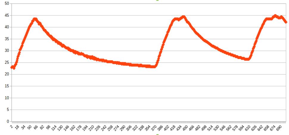
The first code has to be run first and we should wait for the data collection for the decided timeframe. Then the read out code can be run to get the results. As a test I have measured the radiator temperature changes for 6 hours. The outside temperature has dropped from 43 F to 37 F. The beginner temperature in the room was 73 F.
It is clearly visible that the radiator temperature rises very fast when the heating is on, then when it turns off, the temperature drops in an ever smaller scale until it reaches the room temperature. At the second and the third peak there is a slight temperature drop caused by the heating control. As the thermostat reaches the desired temperature it turns off the heating, but the water pump turns on again for a short period to take out the heat from the boiler.
I planned to measure the temperature changes of our electric water heater with an Arduino. Then I wanted to create a chart from the logged data. I planned this as I was curious how the temperature drops and raises as time passes.
Unfortunately because of the insulation there is no place to put the temperature sensor for measurement. This is the thermistor I get from a laptop battery. So this project has to be postponed.
Nevertheless the Arduino circuit is ready, I have the code as well, so I will share it with my readers. The code measures the temperature in the given time intervals, then it stores them in the internal memory. This EEPROM is limited however to 1024 Byte on my Arduino, so I can only save 1024 times, a number between 0-256. If I take a measurement in every 30 seconds, then it is enough to log the data for 8 hours. The data will not be lost if we turn of the Arduino.
An 10000 Ohm resistor and a thermisor is required. The picture shows how to connect the parts.
I have soldered a longer cable on the thermistor for easier handling:
Code for temperature measurement:
#include <EEPROM.h>
// we have to define which analog input we want to use
#define THERMISTORPIN A0
// we have to set the memory address to 0 as the first address
int addr = 0;
void setup(void) {
Serial.begin(9600);
pinMode(13, OUTPUT);
}
void loop(void) {
float reading;
//we take a measurement
reading = analogRead(THERMISTORPIN);
//here we divide it with 4 as we can only save a number between 0-256
int val = analogRead(THERMISTORPIN) / 4;
// we save the value
EEPROM.write(addr, val);
//we jump to the next address
addr = addr + 1;
if (addr == EEPROM.length()) {
addr = 0;
}
//we wait 30 seconds then we take an other example
delay(30000);
}Code to read out the memory contents:
/*
* EEPROM Read
*
* Reads the value of each byte of the EEPROM and prints it
* to the computer.
* This example code is in the public domain.
*/
#include <EEPROM.h>
// the value of the 'other' resistor
// start reading from the first byte (address 0) of the EEPROM
int address = 0;
int value;
double Temp;
void setup() {
// initialize serial and wait for port to open:
Serial.begin(9600);
while (!Serial) {
; // wait for serial port to connect. Needed for native USB port only
}
}
void loop() {
float reading;
// read a byte from the current address of the EEPROM
value = EEPROM.read(address);
Serial.print(address);
Serial.print("\t");
Serial.print(value, DEC);
Serial.print(" ");
//we have to multiplicate it with 4 to get the initial measured value as we saved a value which were divided by 4
value=value*4;
Serial.print(value);
//this is a formula to be used to convert the measured reading to celsius the calculation is from: https://en.wikipedia.org/wiki/Thermistor
Temp = log(((10240000/value) - 10000));
Temp = 1 / (0.001129148 + (0.000234125 * Temp) + (0.0000000876741 * Temp * Temp * Temp));
Temp = Temp - 273.15; // Convert Kelvin to Celcius
Serial.print(" Temperature ");
Serial.print(Temp);
Serial.println(" *C");
/***
Advance to the next address, when at the end restart at the beginning.
Larger AVR processors have larger EEPROM sizes, E.g:
- Arduno Duemilanove: 512b EEPROM storage.
- Arduino Uno: 1kb EEPROM storage.
- Arduino Mega: 4kb EEPROM storage.
Rather than hard-coding the length, you should use the pre-provided length function.
This will make your code portable to all AVR processors.
***/
address = address + 1;
if (address == EEPROM.length()) {
address = 0;
}
/***
As the EEPROM sizes are powers of two, wrapping (preventing overflow) of an
EEPROM address is also doable by a bitwise and of the length - 1.
++address &= EEPROM.length() - 1;
***/
delay(50);
}The first code has to be run first and we should wait for the data collection for the decided timeframe. Then the read out code can be run to get the results. As a test I have measured the radiator temperature changes for 6 hours. The outside temperature has dropped from 43 F to 37 F. The beginner temperature in the room was 73 F.
It is clearly visible that the radiator temperature rises very fast when the heating is on, then when it turns off, the temperature drops in an ever smaller scale until it reaches the room temperature. At the second and the third peak there is a slight temperature drop caused by the heating control. As the thermostat reaches the desired temperature it turns off the heating, but the water pump turns on again for a short period to take out the heat from the boiler.
2016. február 21., vasárnap
Battery capacity measurement with an Arduino - In other words, let's discharge the batteries
Welcome everyone. Who has read my plan - that I will use the Keweisi capacity meter to measure my 18650 cell capacities - knows that I have chosen the Arduino solution, because it gives a more accurate reading. I have spent several days to find out what parts I need and what code do I have to run. I have analyzed several similar projects on the internet. I had to create a simple yet effective code. With my solution it is possible to measure the capacity of 1,2V Ni-MH, Ni-Cd and 3,7V Li-ion or polimer batteries. In fact you can measure the capacity of any battery with this design which has a voltage lower then 5V.
Ingredients:
-a microcontroller, in this case I used an Arduino Duemilanove. Of course it is not a genuine Italian one, it is an aftermarket model from China. I do not think this is still in production, the Uno model is the recent one, but not much has changed on it since. If someone has another type of microcontroller, my connection diagram will not help.
-a resistor. This should be rated at least 5W, so it will be able to bear the load. I have bought a 3,9 OHM and an 5,9 OHM ceramic resistor. The smaller OHM rating we use, the bigger the current will be to discharge the batteries. Why does it have to be 5W rated? It is because if for example the Voltage is 4V and I want to discharge with 1A current then the output is: 4V*1A=4W, this energy is turned into heat on the resistor. If we use OHM's law for calculation at 4V and with 3,9 OHM resistor, the Current will be 4V/3,9OHM=around 1A. Of course as the battery voltage decreases over time, the current will become smaller and smaller. If I use the 5,9 OHM resistor, then at 4V the current will be: 4V/5,9OHM=0,677A. I used the 4V example because a fully charged Li-ion cell gives around 4 volts. This was just an example. But if for instance I want to discharge an AAA 1,2V Ni-Mh battery, the numbers are the following, with a 3,9OHM resistor it will discharge it with 0,307A, which they can bear. I am not sure how much current they can give, but I think 0,3A is enough to prevent overheating. It seems they can bear 1A discharge current as well. You can now calculate the required resistor size if you know with how much current you want to discharge the battery.
-a MOSFET. I used one with three leads called: IRLU8256. This is required to open and close the discharge circuit controlled digitally with the Arduino. It is like a switch, but you can control it from the Arduino code. In case of a Li-ion battery you can turn the discharge off, to prevent over discharging.
Important characteristics: Vds=25V, so it can bear the voltage. Rds=around 5mOHM, here the smaller is better so it has a little resistance. Vgs should be little, so the Arduino 5V power is able to turn the FET on and off.
-a battery to be discharged. You can also buy battery holders, but used magnets to hold the wires on the battery. This is a cheaper solution.
That is all. I have read on the internet, that other designs also measure the voltage on the MOSFET and if there is any loss they use it as well for the current calculation. My MOSFET always gave 0V here, so I left it out.
Warning! The resistor heat up during discharge so it can burn your hand. Of course it will not burn, but it will be hot. Always use wires which can bear the load that you are using. It can happen that the MOSFET stays open and keeps discharging the batteries if we shut the Arduino off or if we stop the code run in the middle. Do not leave it unattended and make sure that it will not over discharge the batteries. I take no responsibilities for the damage this discharger may cause.
If there is no battery connected and the code runs, it will give false Voltage readings.
You can see on the pictures how to connect the wires. Although there are two batteries connected in series on the picture, this is only because there was no other picture in the program. I usually discharge one cell at a time.
Arduino code:
#define MIN_VOLTAGE 950 // mV, the voltage should not drop until this amount. At a Li-ionnál: 3000, with NI-MH:950
int FETPin = 13; // select the digital output pin for the LED and the FET
int BatVoltage = 0;
int STOPI = 0;
float loadCurrent, TotalCurrent, TotalCurrent2, onescurrent;
int sec = 1;
void setup() {
unsigned long PrevTime;
Serial.begin(9600);// start serial port to send data during run to the PC
pinMode(FETPin, OUTPUT);
digitalWrite(FETPin, LOW);
Serial.println("6"); //countdown until the discharge process, I use this time to connect the battery
delay(1000);
Serial.println("5");
delay(1000);
Serial.println("4");
delay(1000);
Serial.println("3");
delay(1000);
Serial.println("2");
delay(1000);
Serial.println("1");
delay(1000);
Serial.println("START!");
int val1 = analogRead(0); // we take an initial test to measure the initial voltage
BatVoltage = map(val1, 0,1023,0,5000);;
Serial.print("Starting voltage in mV=");
Serial.println(BatVoltage + 40); // here I added 40 to the the measured voltage as the Arduino measuread an incorrect Voltage
}
void loop() {
if(STOPI != 1){
digitalWrite(FETPin, HIGH); //here we active the the discharge circuit
int val1 = analogRead(0);
BatVoltage = map(val1, 0,1023,0,5000);;
loadCurrent = (BatVoltage + 40) / 3.9; //at the end of the equation the exact resistor rating in OHM should be changed
onescurrent = loadCurrent / 3.6; //here we calculate the Current amount load in a second
TotalCurrent = onescurrent + TotalCurrent;
Serial.print(BatVoltage + 40);
Serial.print(" mV I=");
Serial.print(loadCurrent); //Current load amount per second
Serial.print(" mA Time=");
Serial.print(sec);
Serial.print(" s Totalcurrent=");
Serial.print(TotalCurrent / 1000); // total mAh burnt
Serial.println(" mAh");
sec = sec + 1;
if(BatVoltage + 40 <= MIN_VOLTAGE){
STOPI = 1;
Serial.println("Voltage is lower then the set min Voltage STOP!");
}
}
else{
digitalWrite(FETPin, LOW);
}
delay(1000); // wait one second, then get next set of samples
}
Feliratkozás:
Bejegyzések (Atom)