2016. március 29., kedd

What an Arduino is and what it can be used for?

It is a printed circuit board built around a controller chip. The chip itself can be programmed depending on what we want to use it to. The big think is that one does not require advance programming skills, it is easy to learn the commans. One can find a lot of help on the internet. The chip can be programmed from a computer through the USB cable. The board has a led and more analog in and output connectors.


What can it be used for? Your fantasy is the limit. I used it for the following so far:

-flashing the led programatically
-measuring temperature
-measuring voltage
-battery capacity measurement

It sends the measured data immideately to the computer on the USB cable, or it can save the data in its memory. If we connect an LCD screen to it, then it can show the data itself. It can be run on battery or from the power from the USB cable or from a power supply.

Of course different projects require different other stuff to be bought. For instance the sensors which data we want to use. One could control a relay depending on the data from the sensors, which for instance would control a lamp connected to the mains power. You can buy so called "shields" to it which expands its capabilities. Wifi shield, bluetooth shiled, SD card shield, sound module, lcd screen. You can connect RF modules to it, you can build an alarm system. You can buy a GPS shield or a GSM shield. These are only some examples.

I have bought mine on 2010.01.07. for 27,51 USD (today it would worth 29,89 USD counting inflation). It can be bought much cheaper today, you can find one for 3,5 USD including shipping from China.

Who have created this wonderful thing? The whole story can be found here. In short, an Italian joungster with his partners has created its prototype back in 2003. Its name was not Arduino back then but it was called "Wiring". Then later there are more threads in the story, who used who's invention, why he used it later, what company he founded. There were quarrels as well as we would imagine. The board was called "Arduino" from 2005. They say, that the name came from a bar where the creators were hanging by at that time. This may be an urban legend.

Anyone can build such a board, they have shared its schematics. Its website is: www.arduino.cc.

2016. március 27., vasárnap

Cheap standing fan from Asia - It is a disaster, terrible, unspeakable, but it works


We have bought this standing fan around 10 years ago. It was not used too much, only on some summers if there was too hot. Unfortunately the summers are getting hotter and hotter in each year. If I remember correctly we bought it on a street market. The street markets sell cheap stuff without a store usually on open spaces. It get tired as the years passed by, of course it was not perfect even when it was new. I have found its blade on the street, because my blade has broken when I accidentally pushed it on the floor. Originally it had blue blades.


Its Brand is Crown, the size is 16 inch, which is correct.


It says: design in Taiwan. It does not matter where it was manufactured... It even has a model number: SF-101. The 60W is true. Q.C. Pass. It means it has passed the quality check. It depends what we call quality and what are the requirements. I think the inspectors either have not inspected this model or it is really what they call desired quality. Does it work or not? It is, so it passed.


I have put some paper under the motor as it resonates so that the whole fan resonates loudly.


Its power consumption:
1. setting: 43W
2. setting: 53W
Afterburner: 61W

Let's see what is wrong with it. The language is Hungarian but the obvious is visible anyway.


I planned to reinforce the legs so it would wobble this much. I have begun to take it apart. This is the sight I saw. It is one thing what would the consumer protection agency say about this, but this also bothers me. This is ridiculous. The incoming two cable, earth and phase are barely touches the pad where they should be securely soldered. They are held there by a feather. If the device falls to the floor for example, these wires can come loose and cause a short circuit. In a better case it only shuts off the fuse in the house in worse case it may catch fire. Horrible.


There is the hole for the wire to solder to, but the factory worker only barely soldered it there. Of course I understand that a factory worker in China solders 5000 from these a day in 14 hour a day for very little money. But anyway...


This is an unhappy standing fan, showing its internal organs.


This crack appeared from the normal usage of the fan.


This capacitor is a mystery. It is broken when the worker secured it, because there was not enough space between the housing and the capacitor, so when the worker tightened it broke down.


As I have seen more and more from the design details, I knew that it is unnecessary to reinforce the legs, as the problem does not lay there. The problem is that the fan blade is not in balance. Because of this, the faster it spins, the more it wobbles. So it does not matter if I reinforce its case or not, sooner or later it would become loose again. So I decided to leave it as it is. I have changed the capacitor, I soldered the wires back and tightened the screws. It stays as it is. On the first setting it does not wobble that much, you should not use the others. :)

I ordered the capacitor from China, it was cheaper with delivery than in a shop in Hungary. It cost 99 USD cents.


I have secured it as it should have been in the factory, I have soldered the wires again.


I have soldered the main cables again and cleaned the button contacts.


I have assembled it again and now it looks the same, works the same... Of course it wobbles less with 10% and will not catch fire. But the main thing is that it works. Please do not buy such a cheap standing fan, there are much better fans for a little more money. Unfortunately I do not remember how much it cost when we bought it.

3.part- Fail of the week - 6600 mAh genuine HP laptop battery teardown

Hungarian version.

To have more 18650 cells, I thought to buy a used laptop battery and get the cells out. It turned out it was not a good idea. However it seemed to be a good offer. For 7 USD a used HP 12 cell laptop battery. I thought that it is not a recent model, but I have not expected this. It arrived with the post, it is a very massive and heavy piece.


It contains Sony cells, great!


Between the picture above and below after more than an hour suffering I was able to open it. It was built from almost a 1mm thick plastic and glued or melted together very well. I even had to use a chisel to open it. This was inside, I like the cell color.


There was no indication about the manufacture date on the outside, however there are signs inside. 2002 or 2003. Oh, no. It may be 13 years old?


The manufacturer put two thermistors into the battery, very clever. One is in the intersection of the left four cells, the other is on the lower four cell. It is better than in the other ones I opened, where only one thermistor was glued to one cell.


I have numbered the cells, so I will know which was where.


Controlling circuit:


The usual heat fuse and two chips which are anonimized.


But here we go! Let's measure the voltage. The three on the right had 2,27V, the other three packs had 1,73V... So I will not be able to use them for security reasons. If the voltage of a li-ion cell falls below 2,5V the inner chemistry gets damaged. The identification codes on the cells tell that they were manufactured in 2003. They are 13 years old! How can this be still around? And who would pay anything for this? I do. But you can't win them all, this buy was a failure. I cut off the two thermistors, so I have now 4 of them. I will take these cells to the recycling center where they already should be for 10 years. I do not wish to open such batteries, it was so hard and I won nothing, but experience.


2016. március 26., szombat

Overview about the consumer battery types

Hungarian version.

AA and AAA Ni-Cd Nikkel-Kadmium battery:

This type was invented in 1898, it was famous until the 1990s when the Ni-Mh became more popular.
1,2V is its nominal voltage, it can only be used limited instead of the normal not rechargeable batteries with 1,5V voltage. They can withstand high current drains. Their capacity is not too big, I do not have good experiences with this type of batteries. They are inclinable to a so called memory effect. If these batteries were not charged fully for a couple of times, then at the next recharge the full capacity became lower. The Cadmium inside them is highly toxic, the European Union has already limited their market.

AA and AAA Ni-Mh Nikkel-metal-hidrid battery:

Their research began in 1967 and they are still popular today, but the manufacturers use Li-ion in more and more places recently instead. Ni-Mh capacity is more than Ni-Cd, they also have 1,2V nominal voltage. They cannot withstand that high drain current as the Ni-Cds. They are not likely to have memory effect. They are also used today in hybrid and full electric cars.

For both the mentioned battery types the electrical devices do not have an easy task to measure the remaining capacity for them. It made me nervous that after recharge I put the Ni-Mh batteries into my camera and it showed after some picture that the battery is now only half full. And as the time went by after 50% capacity the camera said the batteries will be discharged soon. Now I know why this happens. This is in connection with the voltage while they are discharging, which can be followed on the following picture:


On the left is the voltage in mV, on the bottom are the seconds while I was discharging a Ni-Mh AAA battery. It can be very nicely seen that the voltage does not drop consistently like with the not rechargeable batteries, instead in the beginning the voltage drops to 1,2V then it stays there for a long time, and at the end it suddenly drops under 1V. That is why the current capacity cannot be measured accurately by the devices.

They are very irritating at charging as well. There are so called dull chargers for them, which charge them with a small constant current, not watching the voltage in the meantime. They may also overcharge the batteries. On the other hand there are the smart chargers. I do not like them either. Recently the batteries were discharged in my camera and I have put them in the smart charger. One of them was charged for 6 hours, the other was "full" after 10 minutes, however it was empty! I had to discharge it under 1V so the smart charger would recharge it fully. They are a mess.

Li-Ion batteries:

they have begun to develop this type in the 1970s. They went out to the consumer market in 1991 first. They have a much greater power density, they are much lighter than the previous types. They are the stars of the today’s mobile world, they are used everywhere. They are even using them in electric cars.

Their nominal voltage is 3,6-7V. Their voltage drops consistently while discharging so it can easily be measured how much power they have left. They do not have a memory effect, however they cannot be recharged that much like the older types. They are much more sensitive than the others as well. Unfortunately today they can even also be dangerous.

If they get shorted because of some reason, which can be an outside effect or a manufacturing error, they can get hot very fast and a so called "thermal runaway" may begin. This means a sudden overheating which induces a chain reaction inside the cell which can cause an explosion if the battery has a closed sealing package. For instance the 18650 Li-ion cells which are used in the laptop batteries are made in this way. If a cell gets overheated and starts to burn, it will very likely get the other cells to overheat as well. One has to be careful not to leave for example devices with li-ion batteries on the sun or in the car. Their transportation was already limited on the planes because of the fire hazard.

They must not get discharged under a certain voltage (around 3V), because it damages the chemistry inside. They must not get overcharged over the set voltage, as they can overhear and damage the cells. They are very fragile. But there is no better alternative today instead of them. The researches are ongoing to find a safer alternative.

The Li-Po batteries does not differ much from the Li-ion cells, mostly just in their name and the used Anode and Cathode materials. They may have different characteristics.

The recycling of the mentioned batteries is only feasible in huge quantities today, however in the future as the resources will begin to run out on earth, this trash will worth a fortune. After selection of the battery types they are grinded and then on high temperature they get melted and the metals separated then reused.

Opel Corsa C (Vauxhall Corsa C) outside temperature meter replacement

Hungarian version.

The outside temperature sensor got broken in a 2002 Opel Corsa C with left side steering wheel. It first showed wrong amounts, then it just gave two lines as it can be seen on the picture.


The replacement procedure can be followed on the following video:


The sensor can be found in front of the car in the bumper secured with some plastic clips. You can push the sensor inside with the help of a screwdriver from the outside, then the sensor can be unclipped from its cable connection. You can get to it from the top, I have thin hands, but it may be easier from under the car.

It is strange that the cable harness goes on the left side of the car to the front, then from there a cable goes to the right just to connect the temperature sensor. I do not understand this, why have not they put the sensor to the left, so they could have saved money on cable and connections as well. Maybe a car with more extra equipment has something else connected here.

The sensor is a simple thermistor put into a plastic case:


The German quality is not as it used to be, it has broken in 14 years. :)


I do not know what cost 4,5 USD dollars on this. I think it was produced from 30 USD Cents. Of course the profit of the seller is in the 4,5 USD. Although the replacement sensor I bought is not a Siemens product, I hope it will last another 14 years. It only contains a thermistor inside the plastic case, which changes its resistance depending on the temperature. That is all it does.


This picture is from Wikipedia, owner: S 400 HYBRID


The first Opel was manufactured in 1899 in Germany. Opel became a share-limited company in 1929, United States-based General Motors took a majority stake in Opel that same year. General Motors assumed full control in 1931 and today Adam Opel AG is a wholly owned subsidiary of General Motors Company. The Opel Corsa C was manufactured between 2000-2006 in Europe. I think the 1.2 L engine is way too little, it does not have enough power for the car although it produces 75 horsepower. The inside is very durable and the body does not rust after 14 years.

I have already had to fix the dash panel on our car. It happened that while driving all the gauges and lights turned off on the dash panel. If I hit the dashboard with my hand, the gauges turned on again. It was obviously some kind of electrical conduct problem. I had to take out the gauge panel from the dashboard. On its back there was a very bad quality connector which caused the problem. It is so terribly designed that I was shocked. I have put some WD40 contact liquid on the contacts and it is working since.

2016. március 3., csütörtök

Skoda Fabia (an European car brand) hack

Hungarian version.

Once I owned a 2004 Skoda Fabia car. I have got from somewhere the factory service manuals for it. These does not only contain what kind of parts the car has and how to dismantle it, but also gives instructions to read out the main computer data and overwrite it with new values. This particular car was manufactured in the Chech Republic, after German licence, its main computer was built in Italy. This car is a result of a multinational cooperation.


I have ordered from an USB OBD2 diagnostic cable which can be used to connect the car with a computer. Most of the cars have this standard connector since 1996. The service stations are reading out the error codes from the car computers through this connector. I think the whole car control software can be updated as well, however I am not sure about this.

I have begun reading the manuals and I have found some interesting things. I just want to mention the most fascinating ones and the ones I have changed on the car. You are able to test the different parts, some of them have test sequences. For instance you can test the dash panel, it will move the gauges, you can calibrate the fuel gauge, you can turn on and off different relays on the engine, you can change the distance till the next service, and so on. You can change the strength of the power steering. If I wanted to get a sport setting I could have set the RS setting. If I wanted a setting for people with disabilities I could have set it. At the end of the day I have not changed this setting. You can query the data of the factory alarm system. When have it turned on, which sensor triggered the alarm. Was it the internal movement sensor or the trunk sensor? There was a setting what I changed, which controlled the alarm remote control reaction. I turned the option off which allowed the car to blink the turn signal and activate an alarm beep when I disabled the alarm. So now it only blinks the turn signal if I arm the alarm. If the car had parking sensors, you could query the measured distance behind the car and you can calibrate it. You can query the measured values of all the sensors in the car. And there are "millions". Engine speed, engine temperature, inside temperature, fuel level, position level of the electric accelerator pedal and so on. You can query every fault codes from every system on the car. Starting from the airbags, the heating system, the air conditioner, engine, to ABS. Everything. You can spend quite some fun time exploring these. Once I have logged the data of several sensors while driving and a laptop was connected to the car. I was able to collect and save the gathered data. I have changed the behavior of the door locks. I have turned on the function which automatically closes all the doors if the speed rises over 9 Miles per hour. The manual said that this is not activated on the Fabia type cars and it is not activated in the factory, but I have turned it on and it worked beautifully. I think this was only activated on VW cars. I have also activated the function which opened all the doors if I pulled the ignition key out of the socket. 

So with this blog post I just wanted to show that what kind of technology was in a 2004 car and how much can be overwritten or changed on its computer. I think the opportunities are much wider on the today’s cars. It is good in the VW group cars that the manuals are made with German precision and are very well documented. They also use the same standards inside the group brands. So a VW, a Seat, an Audi, or a Skoda has more in common inside than it seems from the outside.

2016. február 29., hétfő

Temperature measurement and logging with an Arduino

Hungarian version.

I planned to measure the temperature changes of our electric water heater with an Arduino. Then I wanted to create a chart from the logged data. I planned this as I was curious how the temperature drops and raises as time passes.


Unfortunately because of the insulation there is no place to put the temperature sensor for measurement. This is the thermistor I get from a laptop battery. So this project has to be postponed.
Nevertheless the Arduino circuit is ready, I have the code as well, so I will share it with my readers. The code measures the temperature in the given time intervals, then it stores them in the internal memory. This EEPROM is limited however to 1024 Byte on my Arduino, so I can only save 1024 times, a number between 0-256. If I take a measurement in every 30 seconds, then it is enough to log the data for 8 hours. The data will not be lost if we turn of the Arduino.

An 10000 Ohm resistor and a thermisor is required. The picture shows how to connect the parts.

I have soldered a longer cable on the thermistor for easier handling:


Code for temperature measurement:

#include <EEPROM.h>

// we have to define which analog input we want to use
#define THERMISTORPIN A0
// we have to set the memory address to 0 as the first address
int addr = 0;

void setup(void) {
  Serial.begin(9600);
  pinMode(13, OUTPUT);
}
 
void loop(void) {
  
  float reading;
  //we take a measurement
  reading = analogRead(THERMISTORPIN);
  //here we divide it with 4 as we can only save a number between 0-256
  int val = analogRead(THERMISTORPIN) / 4;
  // we save the value
  EEPROM.write(addr, val);
  //we jump to the next address
  addr = addr + 1;
  if (addr == EEPROM.length()) {
    addr = 0;
  }  
  //we wait 30 seconds then we take an other example
  delay(30000);
}

Code to read out the memory contents:

/*
 * EEPROM Read
 *
 * Reads the value of each byte of the EEPROM and prints it
 * to the computer.
 * This example code is in the public domain.
 */

#include <EEPROM.h>
// the value of the 'other' resistor
// start reading from the first byte (address 0) of the EEPROM
int address = 0;
int value;
double Temp;
void setup() {
  // initialize serial and wait for port to open:
  Serial.begin(9600);
  while (!Serial) {
    ; // wait for serial port to connect. Needed for native USB port only
  }
}

void loop() {
  float reading;
  // read a byte from the current address of the EEPROM
  value = EEPROM.read(address);

  Serial.print(address);
  Serial.print("\t");
  Serial.print(value, DEC);
  Serial.print(" ");
  //we have to multiplicate it with 4 to get the initial measured value as we saved a value which were divided by 4
  value=value*4;
  Serial.print(value);
  //this is a formula to be used to convert the measured reading to celsius the calculation is from: https://en.wikipedia.org/wiki/Thermistor
  Temp = log(((10240000/value) - 10000));
  Temp = 1 / (0.001129148 + (0.000234125 * Temp) + (0.0000000876741 * Temp * Temp * Temp));
  Temp = Temp - 273.15;           // Convert Kelvin to Celcius  
   
  Serial.print(" Temperature "); 
  Serial.print(Temp);
  Serial.println(" *C");
  /***
    Advance to the next address, when at the end restart at the beginning.

    Larger AVR processors have larger EEPROM sizes, E.g:
    - Arduno Duemilanove: 512b EEPROM storage.
    - Arduino Uno:        1kb EEPROM storage.
    - Arduino Mega:       4kb EEPROM storage.

    Rather than hard-coding the length, you should use the pre-provided length function.
    This will make your code portable to all AVR processors.
  ***/
  address = address + 1;
  if (address == EEPROM.length()) {
    address = 0;
  }

  /***
    As the EEPROM sizes are powers of two, wrapping (preventing overflow) of an
    EEPROM address is also doable by a bitwise and of the length - 1.

    ++address &= EEPROM.length() - 1;
  ***/

  delay(50);
}

The first code has to be run first and we should wait for the data collection for the decided timeframe. Then the read out code can be run to get the results. As a test I have measured the radiator temperature changes for 6 hours. The outside temperature has dropped from 43 F to 37 F. The beginner temperature in the room was 73 F.


It is clearly visible that the radiator temperature rises very fast when the heating is on, then when it turns off, the temperature drops in an ever smaller scale until it reaches the room temperature. At the second and the third peak there is a slight temperature drop caused by the heating control. As the thermostat reaches the desired temperature it turns off the heating, but the water pump turns on again for a short period to take out the heat from the boiler.

2016. február 22., hétfő

Atomic clock on the nightstand

Hungarian version.

My friend gave me a non working digital clock so he said. It works from two AA 1,5V Alkaline battery. When I took it home, I tried to use it with one of the 18650 cells since I have some now and it worked! The curiosity of this clock is that it is radio controlled. This means that it is automatically synchronized by a time code transmitted by a radio transmitter connected to an atomic clock in Mainflingen, Germany. The code of this station is DCF77. This station is 500 miles away from my home and it sends the signal 24 hours a day. It sends the exact time and date as well. The photo of the station is a bit similar to the conspiracy theories American weather controller station. But I do not believe in such things. :) The transmitted signal is repeated in every minute and each second sends its own information bits. Hour, minute, day, month, year. They do not transmit the seconds, I guess the clock automatically adjusts the time to the beginning of a minute.

It is very interesting that they also send the signal of the summer time change and the so called leap second as well. A leap second is a one-second adjustment that is occasionally applied to Coordinated Universal Time (UTC) in order to keep its time of day close to the mean solar time, or UT1. Wiki link. This is something like the leap year. Last year there was a leap second added on 30th June at midnight, when the clocks showed 23:59:60 second instead of 00. But it is sometimes added on New Year’s Eve. The wiki page worth the reading, as this leap second have caused problems for some companies before. For example at the airplane control, as a plane can move 0,16 miles in one second.


Until now there was a 14 bits unused space, in Germany they are just trying to use it for emergency information broadcast. I think this is a good idea. I just need a receiver.

The reception area around Germany:


One can buy a receiver circuit for DCF77, but they are a bit expensive.

It is fascinating that today when there are clocks everywhere and in every device, no one cares about a clock which is as accurate as an atomic clock. How much they would have respected it in the beginning of the last century! It is a bit luxury to have this and it also feels a bit strange, that the clock on the nightstand is as accurate as an atomic clock. And it is for free as well.

What I also noticed that it not always able to synchronize itself with the transmitted signal. For instance my computer's electronic radiation prevents the synchronization. If I put the clock into the window it finds the signal very fast. There is a signal power meter on the LCD, it is very convenient.

Some words about this clock. It's brand is: home by somogyi . The company: Somogyi Elektronic Kft was established in 1991 in Hungary with headquarters in Győr. They practically buying parts and products from China and they put the somogyi brand on them.


Luckily it can handle 4V Li-ion voltage well.

Its power consumption facts:
basic power consumption: 0,01mA
when it is looking for the transmitted signal: 0,29mA
if the backlight shines: 50mA (unfortunately I have broken this when I opened it and I was not able to solder the panel back)

So it consumes very little power, which is consumed by the big display.


One can set two different alarm times on it. It looks like this when opened. It was manufactured at the end of 2007, so it is older than 8 years. The big coil is required to receive the transmitted signal. There is the quartz crystal in the middle, on the right there is the tweeter. There are three chips covered with resin or something as it is cheaper than to box them.

2016. február 21., vasárnap

Battery capacity measurement with an Arduino - In other words, let's discharge the batteries


Welcome everyone. Who has read my plan - that I will use the Keweisi capacity meter to measure my 18650 cell capacities - knows that I have chosen the Arduino solution, because it gives a more accurate reading. I have spent several days to find out what parts I need and what code do I have to run. I have analyzed several similar projects on the internet. I had to create a simple yet effective code. With my solution it is possible to measure the capacity of 1,2V Ni-MH, Ni-Cd and 3,7V Li-ion or polimer batteries. In fact you can measure the capacity of any battery with this design which has a voltage lower then 5V.

Ingredients:

-a microcontroller, in this case I used an Arduino Duemilanove. Of course it is not a genuine Italian one, it is an aftermarket model from China. I do not think this is still in production, the Uno model is the recent one, but not much has changed on it since. If someone has another type of microcontroller, my connection diagram will not help.

-a resistor. This should be rated at least 5W, so it will be able to bear the load. I have bought a 3,9 OHM and an 5,9 OHM ceramic resistor. The smaller OHM rating we use, the bigger the current will be to discharge the batteries. Why does it have to be 5W rated? It is because if for example the Voltage is 4V and I want to discharge with 1A current then the output is: 4V*1A=4W, this energy is turned into heat on the resistor. If we use OHM's law for calculation at 4V and with 3,9 OHM resistor, the Current will be 4V/3,9OHM=around 1A. Of course as the battery voltage decreases over time, the current will become smaller and smaller. If I use the 5,9 OHM resistor, then at 4V the current will be: 4V/5,9OHM=0,677A. I used the 4V example because a fully charged Li-ion cell gives around 4 volts. This was just an example. But if for instance I want to discharge an AAA 1,2V Ni-Mh battery, the numbers are the following, with a 3,9OHM resistor it will discharge it with 0,307A, which they can bear. I am not sure how much current they can give, but I think 0,3A is enough to prevent overheating. It seems they can bear 1A discharge current as well. You can now calculate the required resistor size if you know with how much current you want to discharge the battery.

-a MOSFET. I used one with three leads called: IRLU8256. This is required to open and close the discharge circuit controlled digitally with the Arduino. It is like a switch, but you can control it from the Arduino code. In case of a Li-ion battery you can turn the discharge off, to prevent over discharging.
Important characteristics: Vds=25V, so it can bear the voltage. Rds=around 5mOHM, here the smaller is better so it has a little resistance. Vgs should be little, so the Arduino 5V power is able to turn the FET on and off.

-a battery to be discharged. You can also buy battery holders, but used magnets to hold the wires on the battery. This is a cheaper solution.

That is all. I have read on the internet, that other designs also measure the voltage on the MOSFET and if there is any loss they use it as well for the current calculation. My MOSFET always gave 0V here, so I left it out.

The two other designs I used as inspiration: One, two.

Warning! The resistor heat up during discharge so it can burn your hand. Of course it will not burn, but it will be hot. Always use wires which can bear the load that you are using. It can happen that the MOSFET stays open and keeps discharging the batteries if we shut the Arduino off or if we stop the code run in the middle. Do not leave it unattended and make sure that it will not over discharge the batteries. I take no responsibilities for the damage this discharger may cause.

If there is no battery connected and the code runs, it will give false Voltage readings.

You can see on the pictures how to connect the wires. Although there are two batteries connected in series on the picture, this is only because there was no other picture in the program. I usually discharge one cell at a time.

Arduino code:

#define MIN_VOLTAGE      950   // mV, the voltage should not drop until this amount. At a Li-ionnál: 3000, with NI-MH:950

int FETPin = 13;      // select the digital output pin for the LED and the FET
int BatVoltage = 0;
int STOPI = 0;
float loadCurrent, TotalCurrent, TotalCurrent2, onescurrent;
int sec = 1;

void setup() {
  unsigned long PrevTime;
  Serial.begin(9600);// start serial port to send data during run to the PC
  pinMode(FETPin, OUTPUT);
  digitalWrite(FETPin, LOW); 
  Serial.println("6");	//countdown until the discharge process, I use this time to connect the battery
  delay(1000); 
  Serial.println("5");
  delay(1000); 
  Serial.println("4");
  delay(1000); 
  Serial.println("3");
  delay(1000); 
  Serial.println("2");
  delay(1000); 
  Serial.println("1");
  delay(1000); 
  
  Serial.println("START!");
  int val1 = analogRead(0); // we take an initial test to measure the initial voltage
  BatVoltage = map(val1, 0,1023,0,5000);;
  Serial.print("Starting voltage in mV=");
  Serial.println(BatVoltage + 40); // here I added 40 to the the measured voltage as the Arduino measuread an incorrect Voltage
}

void loop() {
  
  
  if(STOPI != 1){
    
    digitalWrite(FETPin, HIGH);  //here we active the the discharge circuit
    int val1 = analogRead(0); 
    BatVoltage = map(val1, 0,1023,0,5000);;
    
    loadCurrent = (BatVoltage + 40) / 3.9;              //at the end of the equation the exact resistor rating in OHM should be changed

    onescurrent =  loadCurrent / 3.6;		//here we calculate the Current amount load in a second
    TotalCurrent = onescurrent + TotalCurrent;
        
    Serial.print(BatVoltage + 40);   
    Serial.print(" mV   I=");
    Serial.print(loadCurrent);		//Current load amount per second
    Serial.print(" mA   Time=");
    Serial.print(sec);
    Serial.print(" s   Totalcurrent=");
    Serial.print(TotalCurrent / 1000);   // total mAh burnt
    Serial.println(" mAh");
    sec = sec + 1;
    if(BatVoltage + 40 <= MIN_VOLTAGE){
      STOPI = 1;
      Serial.println("Voltage is lower then the set min Voltage STOP!");
    }
  }
  else{
    digitalWrite(FETPin, LOW);  
  }
  delay(1000);  // wait one second, then get next set of samples  
}

The measured capacity is just an estimate, as the higher the discharge Current, the lower the measured capacity will be.

2016. február 18., csütörtök

2.part- 7800mAh genuine IBM Laptop battery teardown - Lenovo T60

Hungarian version.

Welcome everyone. This battery was made at the time when IBM has already sold its laptop business to Lenovo, but the IBM brand was still printed on these products. It is from August, 2006, so it is almost 10 years old. I red this from the battery markings. The battery was used in a T60 laptop. Its teardown was a bit harder than the noname battery I have already written about, because the case is stuck together better.

So the brand is IBM, it is 10,8V and has a capacity of 7,8Ah. As it has 9 cells, it can be calculated that each cell has 2600mAh capacity in it. The cells are Panasonic made and their specification says they have 2550mAh capacity each. If we take it nine times, we get only 7,65Ah capacity, which is slightly smaller than the indicated number on the case.

It looks like this when I have ripped it open. It is interesting how the third row is split a bit. I think this is only a design solution, it has no real purpose. 3 cells in series and 3 in parallel. There is the controlling circuit on the top and there is the heat sensor duck taped to one of the cells. That's all. Well, I have not expected anything else. 6 of the cells had 3,65V voltage, 3 of them had only 2,65V. The guy, from whom I get the cells, told me, that after a charging the battery would not work anymore. We will see if the cells are still in working condition or not.


In the noname battery I previously opened had a nicer controlling circuit. That had a red circuit board and was not covered with such rubber material.


The microcontroller chip is an M37512 together with a 61048FP. If you are interested their specifications you can search on Google. The heat fuse can also be found on the board, it looks slightly different like on the noname circuit.


The temperature sensor can measure only the top right cell's temperature. Maybe it is put there on purpose? Maybe that cell is the mostly used.


This is what is left from the battery, I will use the temperature sensor for other projects.


Here is the capacity list of the cells:

1370
1317
1192
1362
1264
1062
1001
1187
1031
mAh.

How to find out if the cells are in a good shape. For each cell:

1. Measure voltage, if it's less than 2.5v, do not use it.
2. If it gets hot during charging, do not use it.
3. After charging the voltage should be between 4.1v and 4.2v.
4. After 30 munutes if it's fallen less than 4v, do not use it. Note the measured voltage.
5. After 3 days, measure the voltage again, if voltage has fallen more than 0.1v from the recorded voltage, do not use it.

2016. február 17., szerda

1.part- Found aftermarket 4400mAh Laptop battery teardown - Lenovo G450

Hungarian version.

I am planning to build an electric bicycle Li-ion Battery pack. More people on the internet are using 18650 Li-ion battery cells found in Laptop batteries for this purpose. 18650 is a size standard, these are 3,7V cells with significant capacity. I have recently found a laptop battery in a dustbin and I though from the size of the battery that it contains 18650 cells. I have taken it home. It happens regularly that only 1 or 2 cells are faulty in the pack, but the others are still functional. Or just the control circuit shuts it down for some reason. In these cases the battery will not let to charge itself. This is the time when they get in the dustbin. But there are still some usable cells inside which can be used. Of course their capacity does not reach the manufacture capacity, but for hobby and project purposes they are still ideal. They can be also used in a flashlight, storing energy to recharge USB devices and so on. So let’s see.

As it does not have any brand it is a noname aftermarket piece. It is written on the outer shell that it contains Li-Ion cells and it has a capacity of 4400mAh and it gives 11,1V. The sticker on the side tells that it was manufactured in the middle of 2013. It has not been used for too long. Maybe it is because the cells are bad quality or the full battery capacity has decreased to a level that it was unable to give enough power to a laptop, or it would have run only for some minutes.


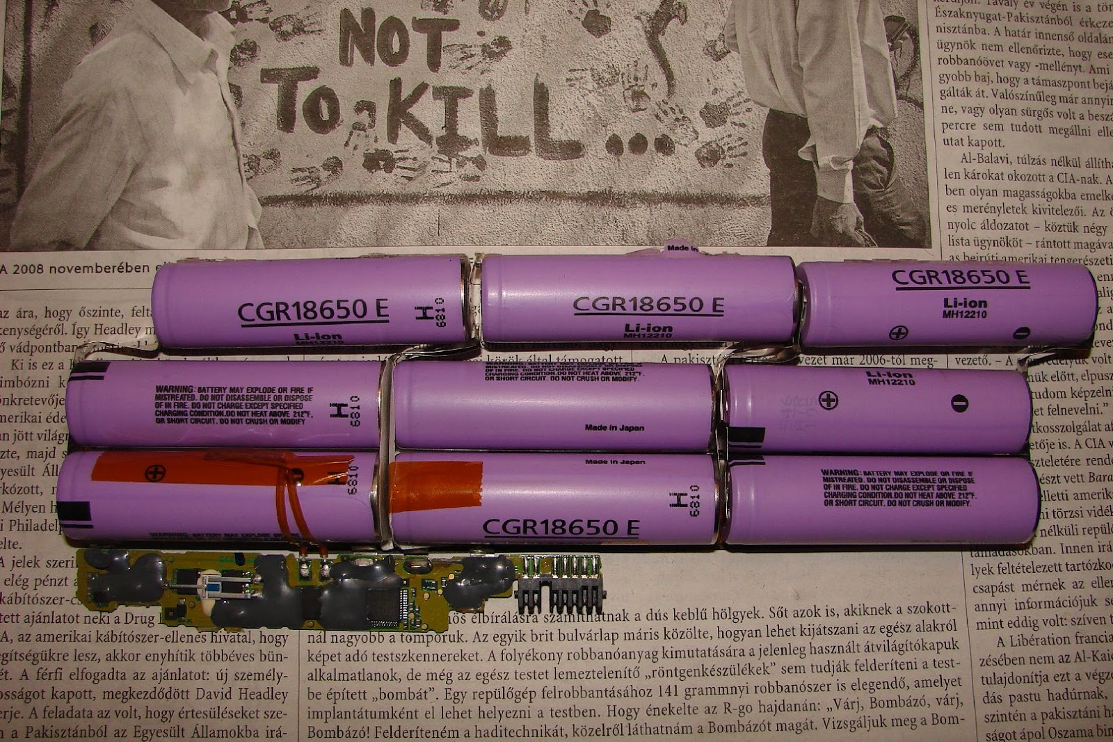
The case was easy to open at the joints. This process requires attention, not to damage the cells or to cause short circuit, as the cells may get overheated or set on fire. There are six cells in this battery.
They seems to be robust compared to an AAA or AA battery, they are bigger and heavier. Three are connected in series and three are connected with them in parallel. 3,7V*3=11,1V as it can be seen on the sticker. From the 4400mAh capacity indicated it is obvious that each cell is rated 2200mAh. The controlling circuit is located on the top right side. There is a temperature sensor duck taped to one of the cells.


It is simple plastic case. What is surprising is that if we take a closer look at this inner side, the initial numbers and markings can be seen from the mould which they used in the factory to manufacture this shape of plastic.


I have cut the cables connected to the controller circuit, then the strip which connected the cells together. We have to take care again, not to cause a short circuit. With the help of long nose pliers the metal strip can be torn off the cells. I used a circular motion to wind it down as I would open a tin can.


The other side of the case. The cells were glued in with hot glue.


The cells seem to be noname, nothing can be found out from their printings. I have searched with Google to SZN cells, a 2200mAh piece cost 3,6 USD in Hungary. The better quality branded ones costs around 5,3 USD each. I was wondering here about the laptop battery prices. A noname similar laptop battery costs in Hungary around 36 USD. A branded one costs around 72-108 USD. But what costs this much on the batteries? One cell costs 3,6USD. 6*3,6=21,6 USD. Plus the package and the controlling circuit. These cannot cost around 14,3USD, because in China they manufacture in huge quantities and in bulk it is way cheaper. So on each of the noname batteries, there is a profit around 10,8-14,4 USD. But I think it is much more. Now let's see the branded ones. Those cost 2-3 times the noname's price. But the branded cells are not cost this much more. Not even the controlling circuit. If we count 6USD*6=36USD if we count the best quality cell. Plus the controller. On the branded batteries there has to be more than 70USD profit on each. This is amazing.

Let's see if the cells are still in working condition or not. They say if a Li-ion cell's voltage drops below 2.5V then it is damaged unrecoverable. I have measured the voltage of these cells and all was on 4,1V! This is normal since while charging they are charged until 4,2V when they are full. So it is possible that all the cells are still functional.


The controlling circuit was made with modularity in mind. It can be seen on the left that this connector part can be changed depending on what type of laptop will it serve. So the other part of the circuit can be always the same. Of course the programming details are changing like how many cells are there, the capacity, the charging current and so on. The temperature sensor is checking if there is an overheating happening. But I think the temperature should be checked on all cells, because what if the one on the left gets too hot, until the sensor on the right senses it, it may be too late. Maybe the branded batteries have different design. The controlling chip is an Atmel MEGA406. You can find its specifications on the internet. There is one more interesting thing on the circuit. The small white cigarette shape with the white putty, it is a thermal fuse. If they reach the melting temperature they cut the circuit. Because it is intact this was not the cause of the dumping.

I have found something interesting on the internet. There is a chance to "reset" the controlling chip, so it will delete the stored information about the charging cycles and errors. It is possible that after resetting the battery would still work for some time. There is a manual about this here. In short it describes that if we search on the internet for the specifications of the controller chip, there is usually a reset leg on it, which in the mentioned case has to be connected with the battery ground wire. This would reset the chip. Please experiment on your own responsibility! Unfortunately I cannot try this on my battery, as I do not have a laptop to test it with.

To be frank I thought the batteries are more complicated inside, but they are not. They are also very expensive compared to what is inside them. I will keep the temperature sensor for future Arduino projects.


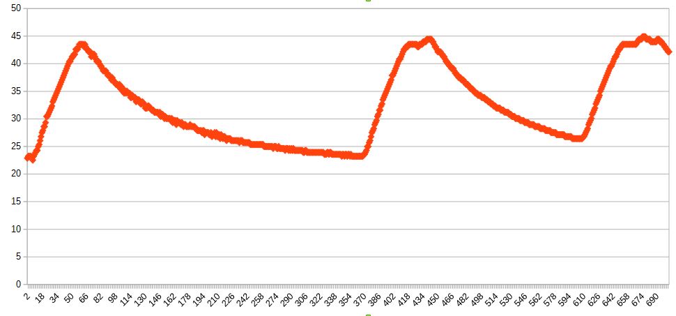
I have measured the cells capacity:

1- 659mAh
2- 51mAh
3- 1238mAh
4- 1303mAh
5- 780mAh
6- 875mAh

When they were new theoretically they had 2200mAh capacity. It is interesting that it has decreased in this magnitude in 2,5 years. We do not know it is because the battery was used too much, or the cells are bad quality cells. But the 51mAh cell proves that it had to perform very badly. I do not think it was capable to run a laptop in this state.

How to find out if the cells are in a good shape. For each cell:

1. Measure voltage, if it's less than 2.5v, do not use it.
2. If it gets hot during charging, do not use it.
3. After charging the voltage should be between 4.1v and 4.2v.
4. After 30 munutes if it's fallen less than 4v, do not use it. Note the measured voltage.
5. After 3 days, measure the voltage again, if voltage has fallen more than 0.1v from the recorded voltage, do not use it.